Aberration
Deviation from perfection in an optical system that results as a product of imperfect ray bending to form an image. Aberrations are inherent in all optical systems. Chromatic aberration, spherical aberration, coma, astigmatism, field curvature and distortion are the most commonly referred to aberrations. Source
Adapter ring
The adapter ring is a circular accessory that has the particularity of having threads on both sides of the filter with two different diameters. These adapter rings allow you to use a circular camera lens filter with a different diameter from the one of your lens. A step-down adapter attaches a filter to a lens that has a filter mount of a larger diameter, while a step-up adapter allows a filter to be attached to a lens with a smaller filter mount
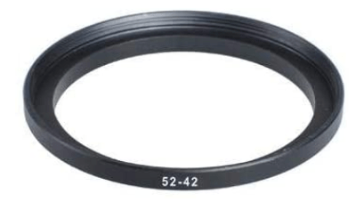

Source, Savazzi (2011)
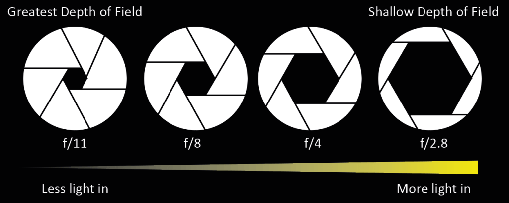
Aperture diaphragm
This diaphragm adjusts the amount of light passing through and is related to the brightness and resolving power of an optical system. This diaphragm is especially useful in width dimension measurement of cylindrical objects with contour illumination, and provides the highest degree of correct measurement/observation by suppressing diffraction in an optimal aperture. Source
Backlash
The amount of play (lost motion) between a set of moveable parts when changing the direction of travel. Source
Barrel Color codes
Microscope manufacturers label their objectives with color codes to help in rapid identification of the magnification and any specialized immersion media requirements. Immersion lenses intended for use with oil have a black color ring, and those intended for use with glycerin have an orange ring. Objectives designed to image living organisms in aqueous media are designated water immersion objectives with a white ring, and highly specialized objectives for unusual immersion media are often engraved with a red ring.
1x – 1,25x – 1,5x Black
2x – 2,5x Brown
4x – 5x Red
10x Yellow
16x – 20x Green
25x – 32x Turquoise
40x – 50x Light Blue
60x – 63x Cobalt Blue
100x White
Source
Chromatic aberration
Chromatic aberration, also known as color fringing, is a color distortion that creates an outline of unwanted color along the edges of objects in a photograph. Often, it appears along metallic surfaces or where there’s a high contrast between light and dark objects, such as a black wall in front of a bright blue sky. Each type of aberration causes different colors of outlines along an object’s edge.
The failure of a camera lens to focus each of white light’s different wavelengths onto the same focal point may lead to blue-yellow, red-green, or magenta-purple fringing. This is due to the refractive index of glass; various wavelengths of light travel through the lens at different speeds, making it difficult for some lenses to focus each hue on the same focal plane. Source
Circle of Confusion
The circle of confusion is the measurement of where a point of light grows to a circle you can see in the final image. Also called the zone of confusion, it’s measured in fractions of a millimeter. The circle of confusion is what defines what’s in or out of focus. This number is also what calculates depth of field. The circle’s size is what affects the sharpness of an image. The smaller the circle, the sharper the image. And the larger the circle, the blurrier. It is often written as CoC. Source
Dead pixels
A dead pixel is a permanently damaged pixel that does not receive any power, which often results in a black spot on the camera LCD. Since digital camera sensors have color filter arrays, also known as “Bayer filters” in front of them, dead pixels do not normally show up as a black spot, but will rather show up of different color than adjacent pixels, or will be slightly darker than adjacent pixels. Source
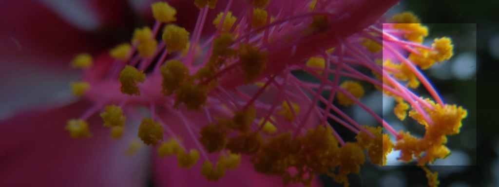
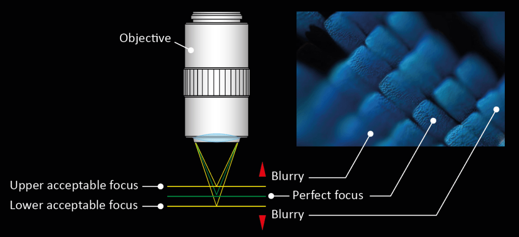
Depth of Field (DOF)
The focal depth refers to the depth of the specimen layer which is in sharp focus at the same time, even if the distance between the objective lens and the specimen plane is changed when observing and shooting the specimen plane by microscope.. The larger the N.A., the smaller the depth of field.
Eyepiece observation (Berek Formula)
±DOF (µm) = (ω * 250.000) / (N.A. * M) + (λ / (2*(N.A.)2)
λ= Radiation wavelength (550nm)
ω: Resolution of human eye (Visual angle: 0.5 degree = 0.0014)
M: Total magnification (Objective mag. * Eyepiece mag.)
TV monitor observation
±DOF (µm) = λ / (2*(N.A.)2)
λ=550nm (Standard wavelength)
Diffuse Illumination
Diffuse, spatially uniform light from an extended source. Used for even illumination of an object. Source
Double image
An image degrading a phenomenon in which an image appears as if it is a double image due to redundant light projection and optical interference within the optical system. Can occur also when the stacking process fail to recombine the sub-stacks. Source
Field Curvature
An optical aberration where focal position changes with field height in a spherical fashion, resulting in flat objects being imaged onto a curved surfaces, as the product of imaging through spherical lens elements. Results in increasing defocus when moving away from imaging axis. Source

Field number and FOV (Real Field of View)
The field number of an eyepiece is determined by the field stop diameter of the eyepiece and it is expressed in mm.
FOV is the area of specimen observable and is determined by the field number of the eyepiece and magnification of the objective.
FOV (mm) = Field number of eyepiece / Magnification of objective
Area of specimen observable on TV monitor
Area of specimen observable on TV monitor = Area of camera image element (VxH) / Magnification of objective
Indication magnification on TV monitor
Indication magnification on TV monitor = Magnification of objective * (Diagonal line length of monitor indication / Diagonal line length of camera image element). Source
Field stop
This diaphragm is used for blocking out unwanted light and thereby preventing it from degrading the image. Source
Finite-corrected optical system
An optical system in which the image is formed only by an objective. Source
Flare
Lens flare is typically seen as several starbursts, rings, or circles in a row across the image or view, caused by unwanted image formation mechanisms, such as internal reflection and scattering of light. Source
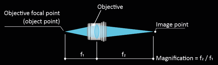
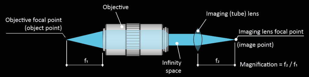
Focal Length
Distance between a principal point and a focal point. f1 is a focal length of an objective, f2 is a focal length of a tube lens. Magnification is determined by the ratio of the focal length of the tube lens to that of the objective. (For an infinity-corrected optical system.)
Magnification of objective = Focal length of tube lens / Focal length of objective
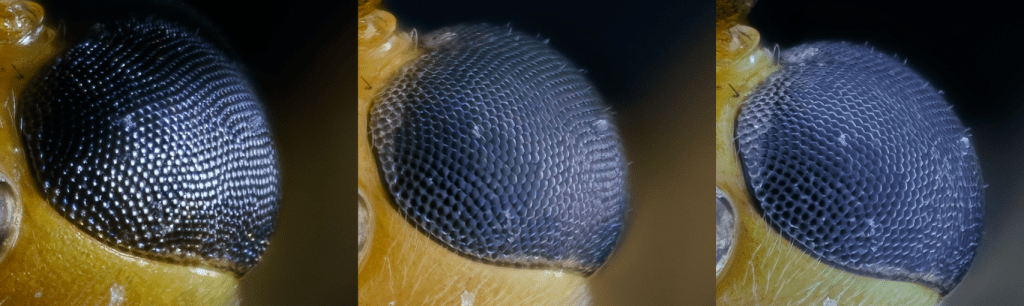
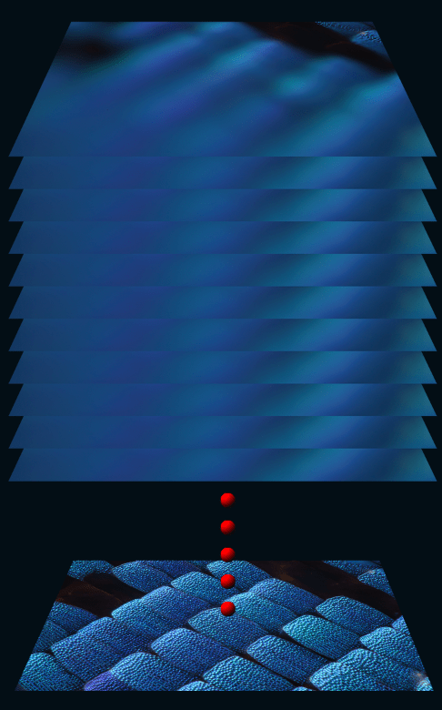
Focus stacking
Focus stacking is a digital image processing technique which combines multiple images taken at different focus distances to give a resulting image with a greater depth of field than any of the individual source images. Focus stacking is widely used in any situation where individual images have a very shallow depth of field; macro photography, optical microscopy, extreme macro photography are typical examples. Source
Hot pixels
Hot pixels only show up when the camera sensor gets hot during long exposures or when the ISO is cranked up above 400-800. Hot pixels are very normal and they will show up even on brand new cameras, although manufacturers do their best to map hot pixels out during the QA process. Hot pixels will appear and disappear over time and if your brand new camera does not have stuck pixels, you can rest assured that you will have them at some point in the future. Source
Infinity-corrected system
An optical system in which the image is formed by an objective and a tube lens with an ‘Infinity Space’ between them, into which optical accessories can be inserted. Source
Magnification
Magnification is the ratio of the size of a specific feature of an object as seen in an image produced by an optical system to the actual size of the feature on the object itself. Thus, lateral magnification, Mx, can be defined as:
Mx = Dimension of the subject / True dimension of the subject
It should be noted that the useful range of perceived visual magnification significantly depends on the maximum resolving power of the microscope system. When the magnification passes beyond the useful range, then no additional details about the sample can be seen. Source
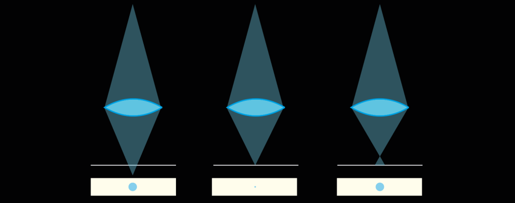
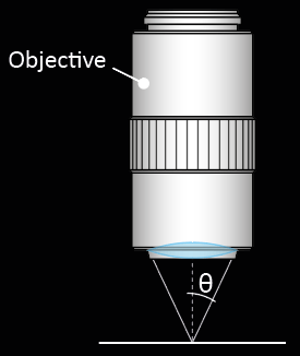
N.A. (Numerical Aperture)
N.A. determines resolving power, depth of field, and the light gathering power. The larger the N.A. the higher is the resolving power and smaller is the depth of field.
N.A.=n * Sinθ
Where n is the index of refraction of the medium in which the lens is working (n=1.0 for air, n=1.515 for oil).
θ is the half-angle of the maximum cone of light that can enter or exit the lens.
Objective Screw Threads
The mounting threads on almost all objectives are sized to standards of the Royal Microscopical Society (RMS) for universal compatibility. This standard is currently used in the production of infinity-corrected objectives by manufacturers Olympus and Zeiss. Nikon, Mitutoyo and Leica have broken from the standard with the introduction of new infinity-corrected objectives that have a wider mounting thread size. Abbreviations commonly used to denote thread size are: RMS (Royal Microscopical Society objective thread), M25 (metric 25-millimeter objective thread), M26 (metric 26-millimeter objective thread) and M32 (metric 32-millimeter objective thread). Source
Optical Corrections
These are usually listed as Achro and Achromat (achromatic), as Fl, Fluar, Fluor, Neofluar, or Fluotar (fluorite) for better spherical and chromatic corrections, and as Apo (apochromatic) for the highest degree of correction for spherical and chromatic aberrations. Field curvature corrections are abbreviated Plan, Pl, EF, Achroplan, Plan Apo, or Plano. Other common abbreviations are ICS (infinity corrected system) and UIS (universal infinity system), N and NPL (normal field of view plan), Ultrafluar (fluorite objective with glass that is transparent down to 250 nanometers), and CF and CFI (chrome-free; chrome-free infinity).
Apochromatic objective and achromatic objective
An apochromatic objective is corrected for chromatic aberration at the red, blue, and yellow wavelengths. An achromatic objective is corrected for chromatic aberration at the red and yellow wavelengths only. Source
Parafocal Distance
Distance between the surface of the specimen and the objective mounting position when in focus. Source

Plan
Denotes an objective lens that produces a flat (planar) image by correcting the spherical aberration/curvature of the field of an achromatic lens or an apochromatic lens. All Mitutoyo FS series objectives are plan apochromat. Source
Polarized observation
It is an observation technique with polarized light generated by a set of two filters (analyzer and polarizer). The polarization axes are perpendicular to each other for extinct. Some specimens located between the two filters give characteristic contrast or coloration according to each birefringence property and orientation. Polarizer is located in the light path before the vertical illumination, while analyzer is inserted in the observation path before eyepiece. Source
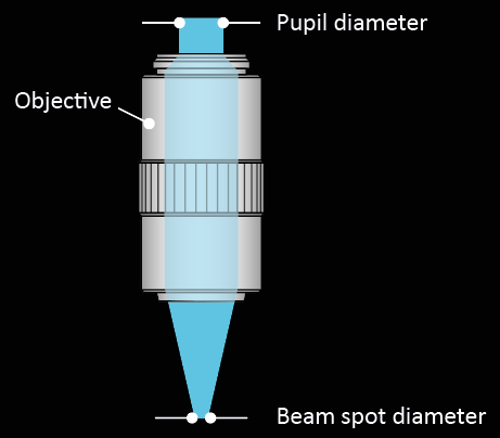
Pupil Diameter and Spot Diameter of an Objective
Pupil diameter
Denotes the maximum diameter of a parallel light flux along the optical axis that can enter an objective from the rear. The pupil diameter is calculated according to the following expression.
ømm =2 * N.A. * f
Spot diameter
If a beam of light with a uniformly distributed intensity enters an objective from the rear, the beam is condensed to a spot of finite size. This size is known as the spot diameter. The approximate value of a spot diameter is calculated from the following expression. Source
øµm =1.22 * λ / N.A
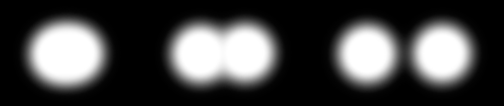
Resolving Power
Minimum distance between points or lines that are just distinguishable as separate entities. The greater the resolving power, the smaller the minimum distance between two lines or points that can still be distinguished. The larger the N.A., the higher the resolving power. Source
Reyleigh formula (µm) = 0.61 * (λ / N.A.)
λ = 0.55µm (visible light)
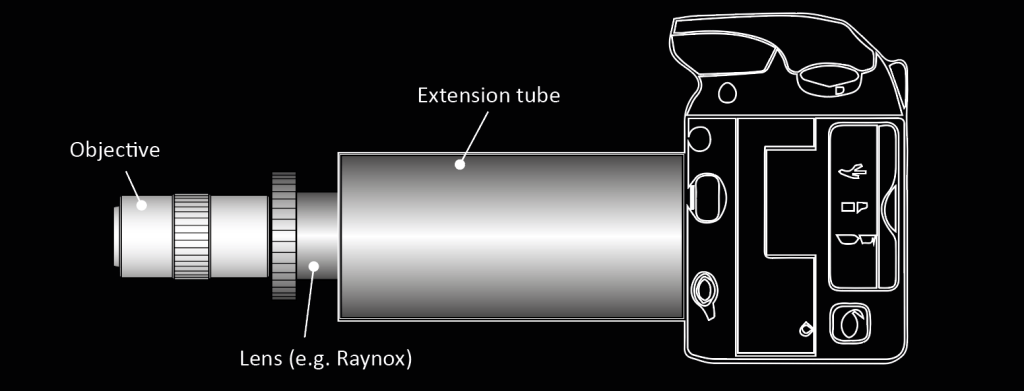
Reverse lens
Reverse lens macro photography is a method of capturing highly magnified images using an interchangeable lens camera, a lens, and an adapter. You turn your lens by 180° so the rear element points outward, then use an adapter to attach the reversed lens to your camera body (or to another lens). Source

Sensor dust
The sensor dust is collected generally on the surface of the anti-aliasing filter located in front of the sensor. Since these dust particles are actually located some distance from the sensor, they are normally out of focus, and become visible in pictures only if their size is relatively large, and/or a narrow lens aperture is used. Source: Savazzi (2011).
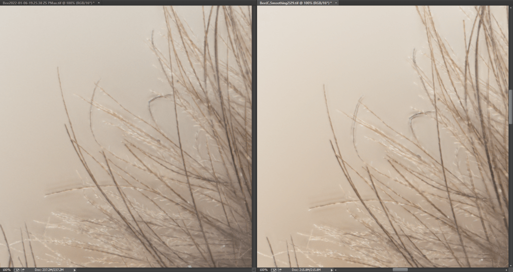
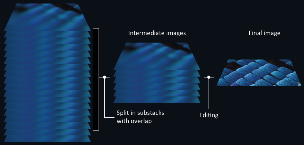
Slabbing
Slabbing is a technique for making it easier to work with stacks that contain large numbers of images. The concept of slabbing is to split a stacking into two big steps. In the first big step you reduce an important volume of images into intermediate images, by stacking sets of 10-15 photos each, with some overlap between sets. Then in the second big step you stack the intermediate images, to produce an image with the full stack combined. When you retouch with slabbing, typically you only have to reach back to the intermediate images (the slab outputs), instead of all the way back to each of the original source images. Source
Stuck pixels
Compared to dead pixels, stuck pixels always receive power, which results in a colored pixel that shows up in the same spot on the camera LCD or on the sensor/images. The colors can be red, green, blue or any combination of these colors. Unlike dead pixels, stuck pixels do not change their color from picture to picture. Stuck pixels are very common, but not permanent like dead pixels – they might disappear over time. Source
Tube Length
This is the length of the tube between the adaptor ring where the objective is mounted, and the top edge of the camera sensor. Tube length is usually inscribed on the objective as the size in number of millimeters (160, 170, 210, etc.) for fixed lengths, or the infinity symbol (∞) for infinity-corrected tube lengths. Source
Tube Lens
A lens used to focus an infinity corrected objective to a senor. Typically, this is an achromatic lens with a 200mm focal length. Source
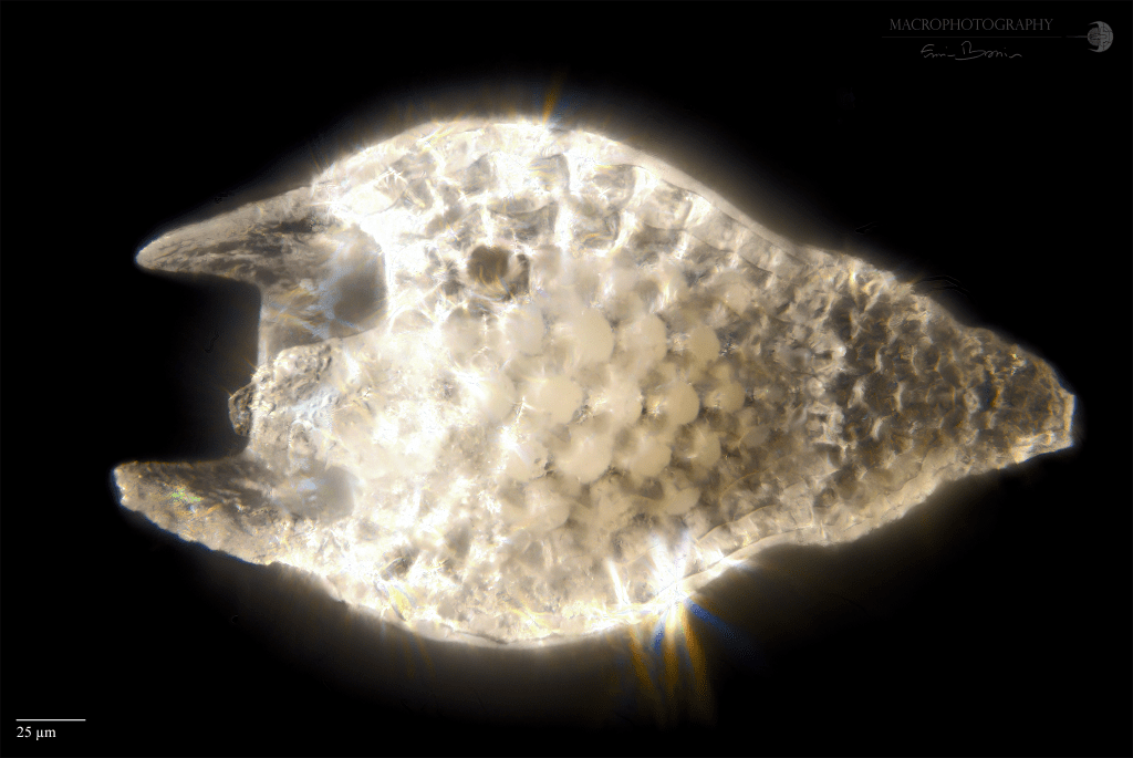
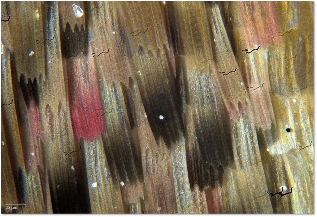
Ultraviolet light
Currently, the most common types of UV LEDs you can find/buy are in the wavelengths of 395 nm and 365 nm, both in the UV A spectrum. One application that is of interest in the field of paleontology, is the study of color patterns in shells, in fact at wavelengths of 365nm, traces of pigments are still present, and UV light makes them glow.
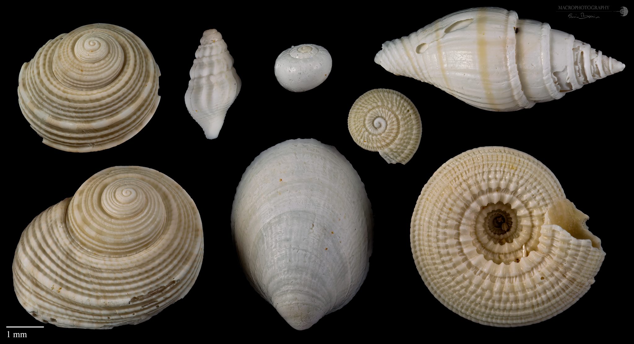
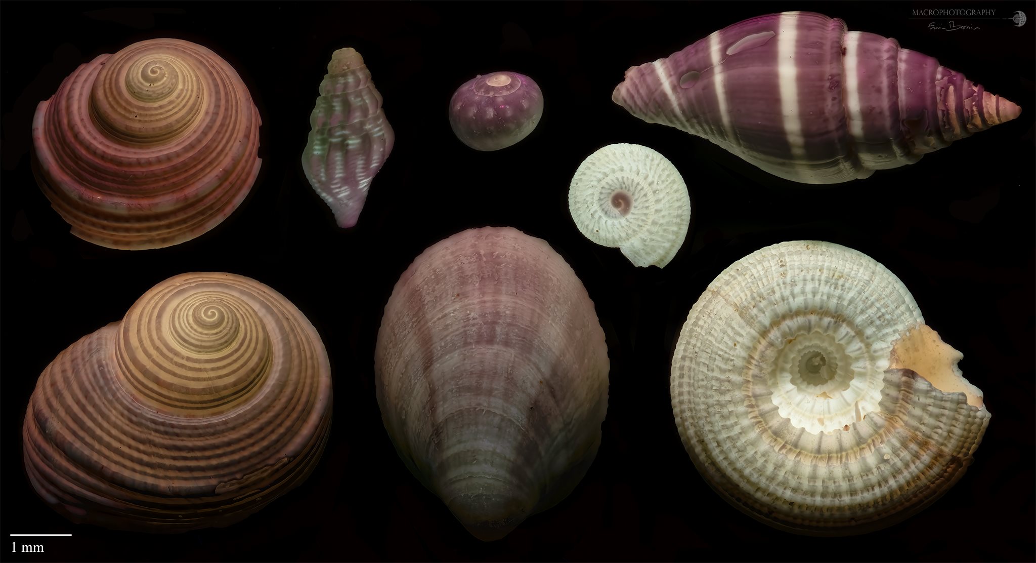
Above, a nice response to the UV of some molluscs shells. These appear in white in visible light (LED), but nicely textured with UV light. Lutetian, Eocene, Cauvigny, Region of Oise (France).
Vignetting
This unwanted effect is the reduction of an image’s brightness or saturation at the periphery compared to the image center. May be caused by external (lens hood) or internal features (dimensions of a multi-element lens). Source
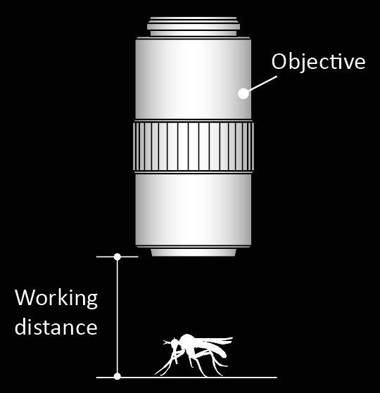
Working distance
Distance between the surface of the specimen and the front face of the objective when in focus. In most instances, the working distance of an objective decreases as magnification increases. Working distance values are not included on all objectives and their presence varies depending upon the manufacturer. Common abbreviations are: L, LL, LD, and LWD (long working distance), ELWD (extra-long working distance), SL or SLWD (super-long working distance), and ULWD (ultra-long working distance). Newer objectives often contain the size of working distance (in millimeters) inscribed on the barrel. Source, Source2
Links
https://www.microscopyu.com/microscopy-basics/microscope-objective-specifications
https://www.mitutoyo.com/webfoo/wp-content/uploads/E4191-378_010611.pdf
https://www.studiobinder.com/blog/what-is-circle-of-confusion-photography/
https://digital-photography-school.com/reverse-lens-macro-close-up-photography-lesson-3/
https://lesdeuxpiedsdehors.com/en/adapter-ring-in-photography/
https://photographylife.com/dead-vs-stuck-vs-hot-pixels
https://www.adobe.com/creativecloud/photography/discover/chromatic-aberration.html
https://www.olympus-ims.com/fr/microscope/terms/
https://www.edmundoptics.com/knowledge-center/glossary
https://www.leica-microsystems.com/science-lab/what-does-300001-magnification-really-mean/
Savazzi, E., 2011. Digital Photography for Science. Close-up photography, macrophotography and photomicrography.698pp.
