The tube system
What does the tube system that I use to acquire the images look like? It took quite some time to define the set up, and lot of tests (lot!) but, looking at the results that I’m able to obtain, I think that this technical step is definitive.
I do not add anything new to the actual knowledge in the domain of extreme macro, and there are lot of websites where you can find more information on “how-to” create your set-up. Here is mine:
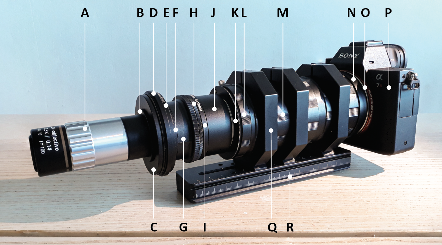
A: Objective
B: 37-M26 adapter (can vary in function of the objective model)
C: 58-37 step down ring
D: 62-58 step down ring
E: 58-42 step down ring
F: 42-43 step up ring
G: Raynox 150 lens reversed
H: 49-49 male to male adapter
I: 42-49 step up ring
J: 42mm MJKZZ-VLE variable length extension tube (adjustable from 20mm to 30mm)
K: M42 – Nikon mount camera
L: Nikon reverse mounting 52mm
M: Extension tubes internally flocked (diameter 57mm, 3x 28mm + 1x 14mm + 1x 7mm) –> the total length (and the number of tubes) can vary in function of the photo camera used.
N: M42 to camera mount
O: 57-58 female to female ring to connect the SONY body camera
P: Camera
Q: Clamps with screws (3x 57mm internal diameter)
R: 160mm long double Arca Swiss compatible plate
“The System”
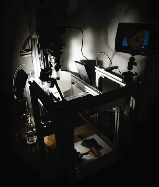
I have been asked to show my acquisition system, the “catafalque” that I set up in order to acquire the images of the minute creatures that you have been the opportunity to appreciate (and for this I thank you infinitely). There is no standard model, and each “macro-photographer” has its own, customized according to the needs, space available, and the subjects to be acquired.
Subject to multiple changes over time, I believe I have reached an end point where no further changes to the system is required. Here it is in his beauty 😊:
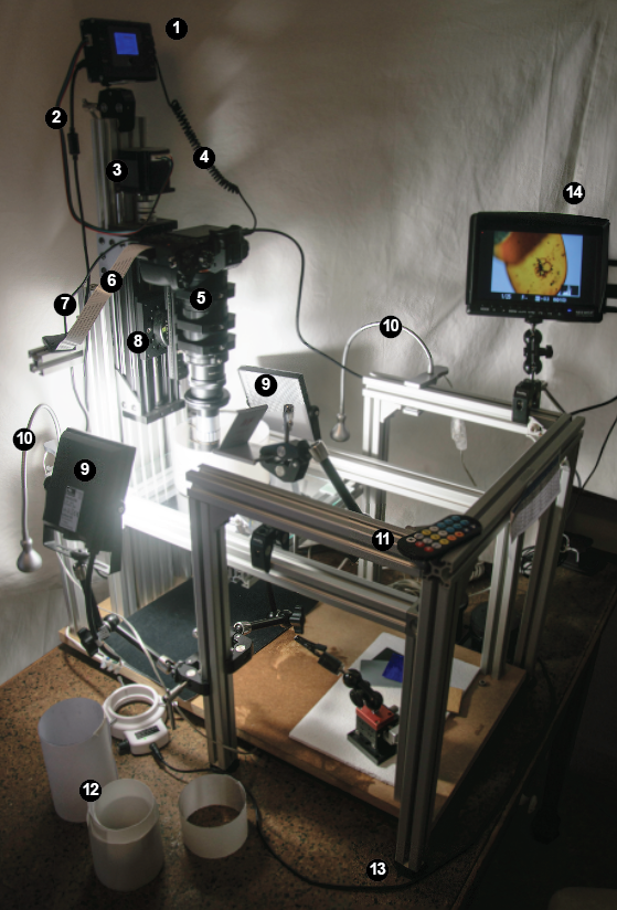
The supporting structure consists of extruded aluminum profiles, with a square section of 30 x 30mm and differentiated into two separate blocks: one that supports the lighting system and the external monitor, and one that supports the motorized rail with the camera and the support for the samples. The separation into two blocks was made to eliminate as much as possible any micro-vibrations created by led panels and support arms. Each foot is equipped with anti-vibration rubber feet (13) and the vertical system is fixed to a composite wooden board 2cm thick. The block containing the lighting can be moved according to the acquisition needs. Being the system “open” it allows a relatively easy access to all components; I have chosen a vertical set-up because the latter allows to acquire correctly the subjects of my interest, positioned on a flat surface. The horizontal acquisition system is instead frequently used for those who photograph subjects such as insects, which in most cases are fixed on entomological needles, and therefore a horizontal system is preferred.
The rail (8) that moves with micrometric steps the camera and the optical tube (5) is firmly fixed on an aluminum V-slot board, allowing to make acquisitions in a vertical position. Un microcomputer with LED screen (1), connected to it and to the camera via a special cable (4), manages the micrometric movement and the number of steps (and therefore the number of images to be acquired), the start and end point, the speed of movement, the pauses between an acquisition and the following, and other parameters. The microcomputer is controlled (11) via an infrared system, a system that eliminates any vibrations that might be present if a system via USB cable were used.
The rail is managed by Nema 23 0.9 degree bi-polar step motor (400 steps/tour) (3), part of MJKZZ’s QOOL 250 model system (www.mjkzz.de), system calibrated to acquire images up to 50x magnification, beyond I haven’t had the occasion to go. This platform is able to carry a weight of 2.3-3 kg in vertical, more than enough to manage my acquisition system (the camera SONY + tube lens and the heavy Mitutoyo objective, weight 1.520 kg).
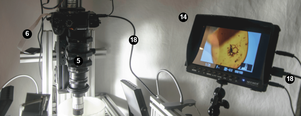
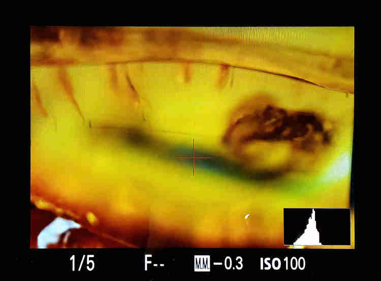
SONY’s mirrorless camera (Model Alpha 7R II) is connected (18) by the micro-HDMI port to an external screen (14) 7-inch LCD 1280 x 800 resolution. This device is particularly useful in order to correctly display the start and ending point of the series of acquisitions, as well as to correctly display the shutter speed and the histogram of the luminance without having to perform special yoga exercises to display everything on the small screen positioned on the back of the camera. The analysis of the distribution of luminance is essential in order to acquire images with a correct balance of light and dark, and not to have photographs too overexposed or underexposed.
The lighting system consists of two 20W LED panels (9) (Dryden model, by Brilliant) and two IKEA LED lamps (Jansjö model, unfortunately now out of production) flexible (10) equipped with clamps, which are extremely useful for illuminating the smallest subjects.
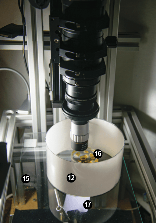
In order to eliminate unwanted light reflections as much as possible, especially when photographing subjects with reflective surfaces (such as beetles, minerals, amber, foraminifera with transparent test, radiolarians… in short, all subjects) one, or a series, of diffusers with variable diameters (8-14 cm) (12) are installed around the subject. The diffuser allows a homogeneous distribution of light, and there are different types (lot of artisanal work) and composition; created according to the type of subject you want to acquire, personally I have used yogurt cans, ping-pong balls, plastic glasses and cylinders wrapped in drawing paper and /or semi-transparent of various sizes. It is important that the paper is white in order not to induce unwanted color variations, and is not very thick in order to avoid altering the colors of the subject and / or lose too much light, the white paper used to make photocopies or semi-transparent for casts are fine.
Resting on a glass surface (15) with felt feet, and at a height of about 20 cm from the base platform is placed the object holder which, in the case illustrated, is characterized by a glass Petri dish (16) in which the amber immersed in glycerin are fixed with plasticine. At the base of the platform is a non-reflective black velvet cloth; this allows for a good homogeneous dark background. In the case of subjects in which the use of a white background (or another color) is required, it is possible to insert colored cards fixed on clams with a moving arm (17), interposed between the base and the glass. These articulated arms equipped with metal end clamps (SmallRig model) are extremely useful for supporting and fixing peripherals to the supporting structure.
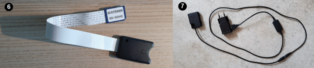
In addition to the external screen that replaces the small camera screen very well, two other peripherals are particularly useful: one is a power supply (7) that replaces the camera battery. This allows you to always have the system powered and not having to extract and recharge the batteries of the camera after 2-3 sessions (sessions that can sometimes last a lot and having the battery low halfway is always not pleasant). A second diabolical instrument is an extension cable connected to the slot that houses the SSD card and where the images are recorded (6). Since it is not possible to connect the camera directly with an external laptop and the processing software (all connections are busy on my system), it is necessary every time to remove the SSD card to insert it into the computer and download the images to be analyzed. This operation carried out repeatedly could risk damaging the internal system, and this would cause much weeping and gnashing of teeth. Instead, using this extension, which also facilitates access to the slot, allows you to safeguard the mechanics.
However, subject to continuous modification, this system is extremely flexible and allows to acquire subjects with dimensions from centimeters to sub-millimetric without any problem.
The Depth of Field
In this section I introduce an outrageous subject, one that often makes for sleepless nights and brings adrenaline rates close to hospitalization… that is: how many shots does the camera need to take in order to get a subject fully in focus when using a microscope lens?
Dozens? Hundreds? How many?
I do not enter into the subject of optics and physics of light (also because I haven’t the knowledge), but at least one thematic to understand how to parameterize our system must be addressed, that is to understand what the Depth of Field (DOF) is.
In simple terms, the DOF is the distance between the nearest and furthest part of the object with respect to the lens, that is acceptably sharpened and in focus. If you move further away (or get closer to the lens) the image will be out of focus, blurred, and you will need to move the lens (or the subject) to see more of it.

The value of DOF is a function of the numerical aperture of the lens (NA), the magnification (M), the resolving power of the human eye, the wavelength used. Some values (such as wavelength and resolving power) are constant, while NA and M are technical characteristics of the lens used and are often indicated on the barrel, or otherwise easy to find at the manufacturer.
The numerical aperture is the value that most affects the DOF, which is inversely proportional, so that a higher value of numerical aperture corresponds to a lower value of DOF, and vice versa.
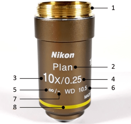
General description of a lens: 1- Mounting thread; 2- Type of correction on optical aberration (Optical Aberration Correction); 3- Magnification; 4- Numerical aperture; 5- Image distance; 6- Working distance; 7- Cover glass thickness; 8- Magnification color code.
There is a simplified formula that is generally used when using objectives for microscopy and that is expressed as DOF = 0.00055/(NA * NA), this formula and other interesting tables are available on the site : http://zerenesystems.com/cms/stacker/docs/tables/macromicrodof .
This formula works if the objective is used at the nominal magnification. If you would like to use a 5x objective at 10x, the DOF will change, but also the quality of the image, increasing the risk to have more vignetting, chromatic aberration, and a general loss in image quality.
Based on the value obtained from the above formula, we can set the movement of the motor and the advancement of the acquisition system. According to the size (the thickness) of the object, you’ll need to acquire a greater or lesser number of steps; a relatively flat object will obviously require a lower number of steps than a spherical subject. You can consider the single steps as lasagna slices that make up a nice baked pasta. Every single slice of lasagna is a step, and the whole corresponds to what you have in the dish (never enough…)
Keep in mind that, in order to have the whole subject in focus, we must consider an overlap between successive steps of a value of 20-30%. In this way we can make sure to get a good final result, at the expense of a few extra images (and that never hurts). The process of merging frames is done by specialized software (Helicon Focus and Zerene Stacker are the most widely used), and the partial overlap between successive images allows the software to be able to “stitch” the parts together, resulting in a complete in focus subject.
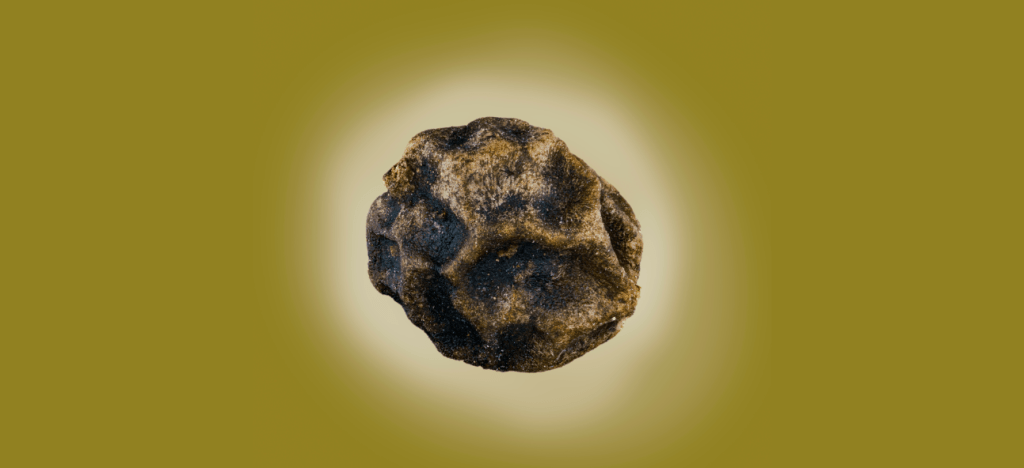
As an example, I’ve acquired a grain of black pepper with three different lenses, but with a magnification approximately similar: a russian LOMO 3.7x, a PLAN 4x and a japanese Mitutoyo 2.5x (pushed to ~4.7x).
The result of the three acquisitions can be seen in the following picture:
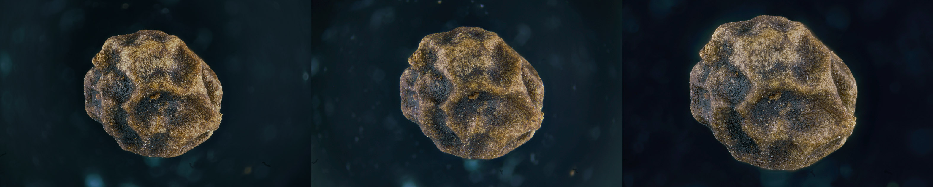
Although the result is almost the same if you compare the three images obtained (I do not enter into the quality of the objectives, perhaps the subject of future discussion) it is important instead to compare the number of images that were required to acquire the entire surface of the subject (the total includes an overlap between successive steps of 20%):
Mitutoyo “4.7x” NA= 0.14 (DOF of 28µm) 287 images
PLAN 4x NA= 0.1 (DOF of 55µm) 155 images
LOMO 3.7x NA= 0.11 (DOF of 45.4µm) 158 images
This difference, which is also notable between the Mitutoyo “4.7x” and the other two objectives, is justified by the fact that the numerical aperture NA of the Mitutoyo is 0.14, while the LOMO is 0.10 and the PLAN 0.11, and we have seen that a higher value of NA corresponds to a lower value of DOF
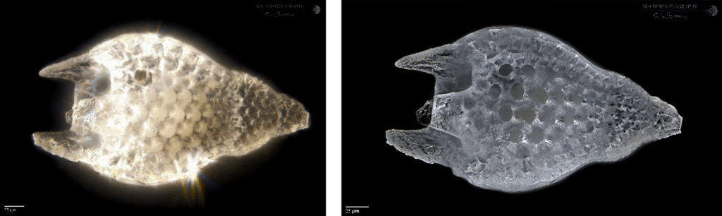
Comparing the image of a frame acquired with the Mitutoyo (left) and the same image acquired with the LOMO (right) we can see that the DOF is lower in the Japanese lens, requiring a greater number of steps – and frames – to cover the entire subject, compared to the Russian one. The latter has a higher DOF and, consequently, there are fewer images to capture. The white band indicates approximately the area where the image is acceptably sharp.
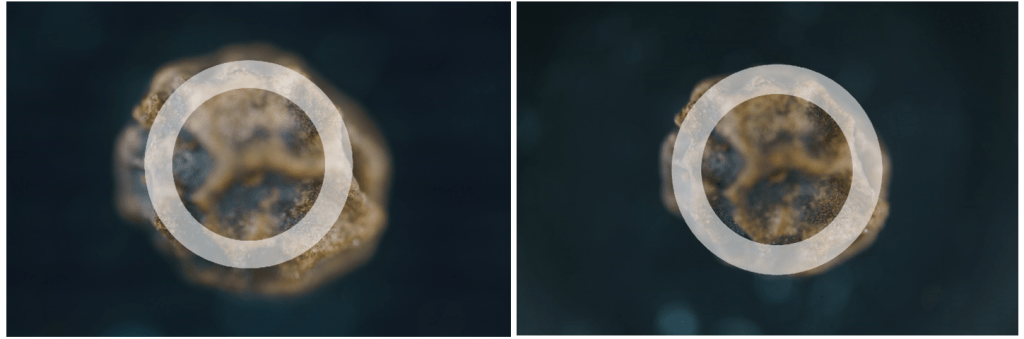
In conclusion, it is important to know these simple parameters before embarking on capturing an outrageously high number of frames (which will take up Gb of space on your disk and waste of time to process the images).
Experience will then allow you to refine your technique and optimize your acquisition processes.
Happy stacking!
Post-processing
How much does the processing of an image affect its quality compared to one that comes out from the stacking software used?
Do standardized techniques exist?
Before getting into the heart of the matter, it is necessary to make a brief introduction about the two leading image stacking programs: Helicon Focus and Zerene Stacker. [I haven’t the Zerene software installed on my computer, so forgive me for any mistakes that I will be quick to correct if necessary].
The following image shows the Helicon Focus and Zerene Stacker programs running:

Data Input:
Helicon Focus can import files in .JPG (8 bit), .TIF (8 bit or 16 bit), .DNG (Digital Negative, a format developed by Adobe, open) and many RAW formats created by the various manufacturers of the most popular cameras (.ARW for Sony, .NEF for Nikon, .CR3 for Canon…), while Zerene Stacker only allows you to import .JPG (8 bit), and .TIF (8 bit or 16 bit) formats.
The problem with the .TIF format is that not all cameras allow you to save images directly in this format, so if you want to keep intact the 16-bit encoding (and not use the .JPG format), you must convert all frames from RAW to .TIF, before importing in Zerene Stacker the series of images to be compiled.
Data Output:
The format exported of the compiled images is slightly different in the two software, with Helicon Focus able to export files in .DNG (16 bit), .JPG (8 bit), and .TIFF (8 bit or 16 bit), while Zerene Stacker only .JPG (8 bit) and .TIFF (8 bit or 16 bit). Please note that the export in .DGN format is possible only if you have installed the Pro license in Helicon Focus.
Why complicate your life using a RAW format and not working with the lighter and easier .JPG? I will partly summarize what is written on Wikipedia about the benefits of using the RAW format in photography.
Using the JPG format means that the image we receive has already undergone a process (total or partial) of color balance, saturation, contrast, and sharpness. The parameters are calculated automatically or defined by the photographer BEFORE the image is captured, so it is no longer possible to make profound changes on these values. Exporting in RAW format allows to get access equally to images that are already pre-processed by the camera software, but these settings are completely manageable, editable, and can be improved during the post-processing. Of course, this requires an additional step before importing the image set into our stacking software.
The RAW format has considerable advantages over the JPG format, such as:
– It has many more shades of colors (4096 to 16384) than the 256 shades of a compressed 8-bit JPG;
– It has higher image quality. Since all image treatments (such as gamma correction, demosaicing, white balance, brightness, contrast…) used to generate pixel values are done in one pass on the basic data, the resulting pixel values will be more accurate and will show less of the posterization phenomenon (defined as an effect applied to an image which it is compressed, reducing the number of color levels, increasing contrast, but decreasing the nuances);
– The standardized steps performed by the camera, such as sharpening and noise reduction, are avoided to leave the operator free to optimize these parameters;
– JPG images are usually saved using a compression format that corresponds to a certain loss in quality. RAW formats generally use a compression technology that does not alter the pixel value (lossless), without data loss and quality;
– Exporting in .DNG or .TIF format (16 bit) allows to have an output file with much more important dynamics, and this is particularly interesting if you want to highlight image sectors that have dark or light areas. Moreover, in the professional printing phase (large posters and in CMYK color space), the JPG format risks to present in correspondence of high chromatic contrast areas artifacts due to the compression process;
– Finer control. RAW image conversion software generally allows the user to modify more parameters (such as brightness, white balance, hue, saturation, etc.) and manage them with more freedom. For example, the white point can be set to any value, not just discrete defaults values such as “daylight” or “incandescent”, and similarly the colorimetric calibration, which is particularly important when you want to keep the real colors of the photographed subject;
– It is possible to use different demosaicing algorithms, an operation that allows reconstructing the color representation of an image starting from the raw data obtained from the sensor of a digital camera, and not only the one encoded in the camera itself;
– The content of the RAW files contains more information and potentially higher quality than the converted .JPG results, where the rendering parameters are fixed, the color gamut is reduced and there may be quantization artifacts (due to the compression technique with loss of information and colors);
– Transformations of luminance values, for example, if you increase the exposure of a strongly underexposed photo, result in fewer visible artifacts than if you perform the same process on an already rendered image;
– All changes made to a RAW file are non-destructive; that is, only the metadata that controls rendering is modified to make the different output versions unchanged, leaving the original data unchanged.
There are, of course, disadvantages to using the RAW format:
– RAW file sizes are typically two to six times larger than JPG file sizes, a function of course of the level of compression. This requires the use of SSD memory cards with higher storage volume and fast access; you must also take into account that a macro-extreme image capture session can involve hundreds of images and easily occupy a dozen (or more) of Gigabytes;
– The different RAW formats are not always compatible with processing software (which must always undergo to frequent updates), while the .DNG format, a potential candidate to become a universal standard format, has not yet been officially adopted by all camera manufacturers. This has led to the creation of several RAW formats in time, and the abandonment of others, following the evolution of data storage technology;
– The time required in applying the usual workflow in image processing is an important factor when choosing between unprocessed and ready-to-use image formats. With modern stacking software, the time required to process unprocessed images has been greatly reduced, while still requiring additional steps in the workflow compared to using a simple JPG.
Working with a RAW file (in Camera RAW):
RAW files are generally easily imported within Adobe products, and despite having a relatively old version of this software, I have never had any problems whatsoever reading and viewing files in Camera RAW. However, there are many platforms, open-source or not, that can import and process RAW formats without any problem.
The operations performed, such as correcting exposure values, color distribution, contrast, light and dark levels… are automatically saved in an .XMP file that will accompany each RAW image. This file contains all the information (metadata) about the changes made to the images, changes that do not affect the source image.
After this operation, you can import the files into Helicon Focus and start the compilation process. Warning! Helicon Focus does not recognize the .XMP file as such, so when you view the image in this software, it will appear as if it was not processed on Camera RAW.
After the stacking process is finished, the result is exported in .DNG format and opened again in Camera RAW. The image is displayed applying the parameters defined before importing the individual files into Helicon.
Working in this mode means that you don’t have to convert RAW files to .TIF or .JPG format once they have been exported from the camera, and consequently save time in processing the data, although the calculation process in Helicon Focus is slower compared to using a JPG format.
Regardless of the software used, the treatments that are applied to the final image are in principle very standardized, but depending on the subject photographed and the level of ability acquired by the photographer.
Below I will briefly illustrate the steps I perform to calculate a decent image.
1– Preparation Operation:
Correct positioning of the light source(s). This deserves a separate chapter that I will create soon on another page;
Calculation of the number of steps required to cover all the subject (operation automatically done by the computer connected to the rail and the camera) and function of the size of the single step;
Choice of shooting times. Here the luminance values in the histogram must be as centered as possible, and the curve (must tends to be) a Gaussian one.
This histogram is generally accessible on the camera screen;
2– Depending on the size of the subject, the lenses used, the detail you want to get, the time required to complete the acquisition can vary from ten minutes to more than an hour;
3– The files in RAW format obtained during the acquisition session are imported into Camera RAW where you start to make changes to the image.
4– The correct exposure, to optimize the luminance curve of each channel, is one of the first operations. This allows me to obtain a good image dynamic over (almost) the whole range of pixel values, from black (which is located on the left of the histogram) to white (which is located on the right of the histogram).
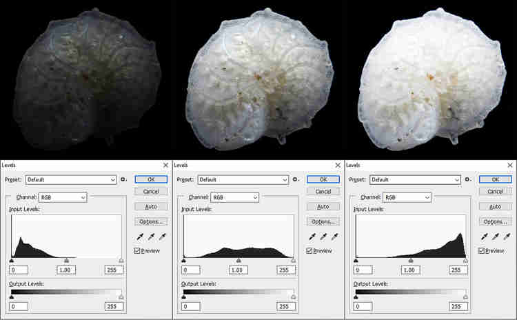
Generally, I do not tend in this phase of work to move the extreme values of the curve at the ends (i.e. to under-saturate or over-saturate if I am in the presence of a black or white background), but I leave a 5-10% area without values. Balancing is done using the sliders that handle the highlights, white, shadows, and black. The values of Saturation, Vibrance, Texture, Clarity, Dehaze are not modified and will be modified after calculating the stack. Modifying these values risks increasing the visibility of background noise in every single frame, affecting the final quality of the stack.
5– Once finished setting the parameters, the operations are saved in a metadata file in .XMP format (using Camera RAW).
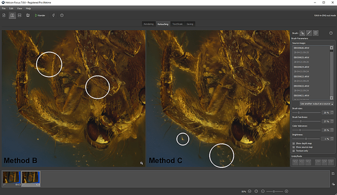
The RAW files are now ready to be imported into Helicon Focus; as previously stated, this software does NOT recognize the .XMP file, so the changes made in Camera RAW on the images will not be displayed on the screen. When stacking I use both Method B and Method C (in Zerene Stacker Method B corresponds to DMap, and Method C to PMax). This allows me to compare the results obtained with the two methods, and move on to the retouching process, replacing the best-calculated areas with one method with those of the other. Generally, I use Method B (less subject to reflection of shiny surfaces), to which I add the parts that are better represented with Method C (that offer a better rendering in correspondence of complex superimposed structures). The Helicon retouching tool is very simple and efficient.
In the next image, I have highlighted some differences that can be observed using the two methods B (left) and C (right).
7– The file, once the correction process is finished, is exported in .DNG format and imported back into Camera RAW. The software recognizes the presence of metadata in .XMP format, and displays the file with the corrections made in the initial phase of treatment. If necessary, now you can make operations like rotate, crop, increase or decrease of contrast and saturation levels. Finally, I switch to Adobe Photoshop (PS).
8– Generally the first operation I perform is the removal of the sensor noise, using the program Topaz DeNoise (it can be accessed either as a filter, starting from PS, or as an independent platform). This software allows you to remove noise while also increasing contrast using artificial intelligence algorithms. I find it excellent. The noise is generally not particularly visible, capturing images at 100 ISO, but often the graininess of the digital image emerges when working on parameters such as contrast and texture.
9– The second operation is the removal of any traces, spots, dust, scratches, or anything else that make the image unattractive or “dirty”. PS allows you to remove many of these imperfections without major problems, and the main tools used are the Spot Healing Tool, the Clone Stamp Tool, the Brush (paying attention to correctly sample the background color and correctly adjust the values of Opacity and Flow of the brush), and for some halos that can occur when there are abrupt color changes (such as from the white of a shell to the black of the background) also the Burn Tool. You should not go “heavy-handed” because the changes, if you do not pay attention, will be easily visible once you exceed a certain “threshold” of correction.
Application of the Spot Healing Tool:
Application of the Clone Tool:

Application of the Brush Tool:
Application of the Burn Tool:
10– The retouching process comes to an end with the application (if necessary) of the Sharpen AI filter (also from Topaz). Again, the results that this software allows to obtain are very impressive.

11-Finally, we proceed to the positioning of the reference scale (should always be mandatory). The procedure for calculating the scale as a function of the magnification used is simple on PS, but I will return to the subject in a later post.
12– The file is saved in .PNG and .PSD format and archived for future use.
What is described in these pages may vary depending on the subject being photographed. A 500µm diameter foraminifera will require an acquisition process that will undoubtedly be different from that required to photograph a 5cm long insect with antennae, spines, and bristles on its carapace.
Image created on Helicon Focus (left), and after processing on Photoshop (right):
Techniques and results evolve with time and skill, which is fatally acquired by trying and retrying [so it was useless to read these pages, to learn you “only” have to do].
The important thing is to never let your guard down, and patience rewards.
Happy stacking!
Cylindrical LED lighting system
One of the main problems to be faced and that must be solved, for those who work with macro-extreme systems, is to be able to operate in an environment in which there is a diffusion of light as homogeneous as possible. The problem is not only the shadows that, in some cases, can be undesirable, but in particular the reflections that are created by specular surfaces, from the metallic carapace of beetles to the hyaline thecae of radiolarians and foraminifera, to the shiny surfaces of crystals and ambers. The result of insufficient light diffusion can be observed most clearly when images are compiled (stacked).
As can be seen in the next image, the same subject was photographed without a diffuser (left) and with a cylindrical diffuser on the right, using an ordinary yogurt can of opaque white plastic.
In addition to eliminating the reflections present on the surface of the radiolarian, the details of the surface are better highlighted, allowing a more detailed analysis of the morphology of the organism.
The use of diffusers characterized by sheets of white paper, tracing paper, yogurt cans, sheets of opaque or semi-transparent plastic, sometimes implies an important loss of light, with the consequent need to use longer exposure times, and to be more subject to external vibrations that would make the image blurred and unusable.
Thanks to the expertise and availability of the OGGLAB laboratory (https://www.facebook.com/oggl.lab), I have the opportunity to test a new lighting system that uses LED technology.
The system is characterized by an Anticorodal aluminum cylinder (aluminum alloy with magnesium, manganese, and silicon, characterized by good mechanical properties and excellent corrosion resistance) with a diameter of 75mm and a thickness of 2.5mm. The decision to use an aluminum housing was made to better dissipate the heat that is necessarily produced by the LEDs when they remain on during the entire process of photographic acquisition, that can also exceed 30 minutes, depending on the subject that is photographed.
The dimension of the system in 100mm in diameter (external) and 85mm in height.
The LED strings (4000-4500K) are organized in four vertical and two horizontal groups, for a total of 252 LEDs and a power of 15.5W. The following photo shows the LED strips before being mounted and how they look once inserted into the cylinder. The diffuser is removed allowing to show the LED lights, but once installed the system is ready to be used.
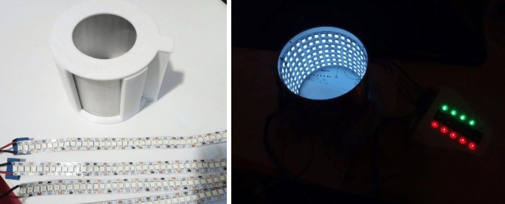
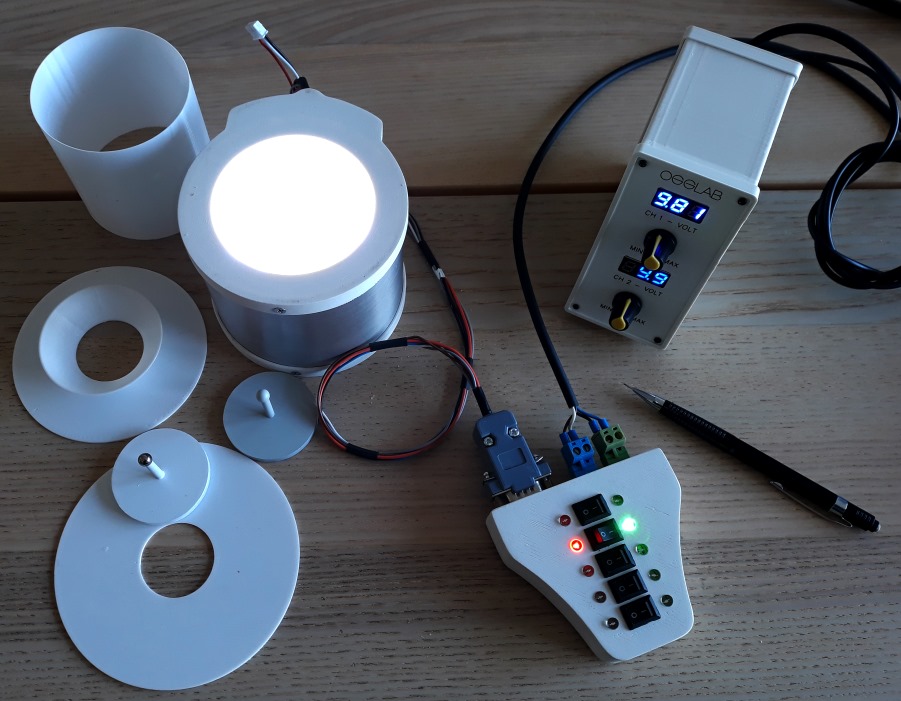
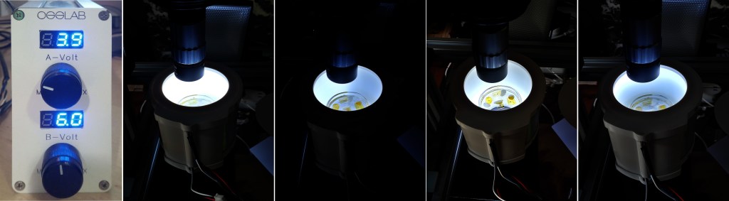
An interesting feature, which is implemented in the lighting system, is the ability to manage via a two-channel power supply with variable voltage and step-down controller, the amount of light inside the cylinder, both channels have the possibility to decrease/increase and/or turning on/off the power of the LEDs along the vertical half of the cylinder. This allows you to have a variable and directional lighting on the subject in case it is necessary to have less illuminated sectors and give a sense of “three-dimensionality”. This function is particularly interesting if you work with ambers that have irregular surfaces and you want to eliminate reflections as much as possible.
In the image below, in the second image, you can see the cylinder completely illuminated, half illuminated in the third image, and the lower and upper parts in the fourth and fifth images, respectively.
A switch button box also allows the four levels of LEDs inside the cylinder to be turned on or off. So not only is it possible to manage the light source from one side or the other, but it is also possible to work using different levels; the system, therefore, allows a total freedom of three-dimensional lighting.
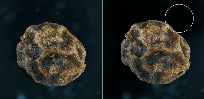
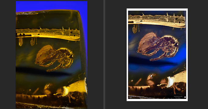
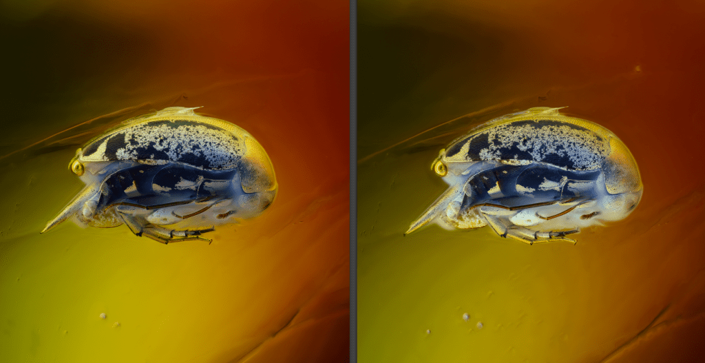
In the next image the same subject (a Mordellidae encased in a Baltic amber) is lighted only on the dorsal side (half cylinder has the LED’s OFF) and with all LEDs lighted ON (right image).
A fifth switch allows access to a vertical lighting, with the implementation of a cover with LEDs, perforated in the center to give access to the objectives (this part not yet implemented).

A PETG diffuser to ensure sufficient light transmission, covers the LED strings, allowing an optimal light distribution.
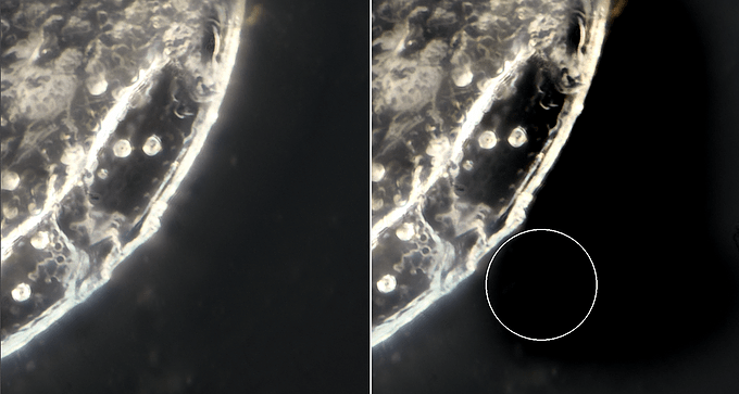
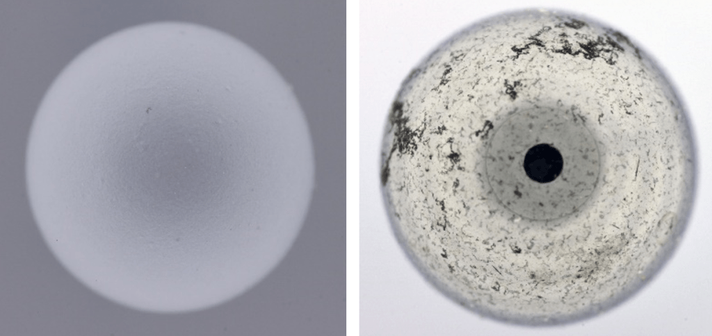
A laboratory test carried out using spheres installed on a plastic column has provided extremely encouraging results on the distribution and diffusion of light inside the cylinder.
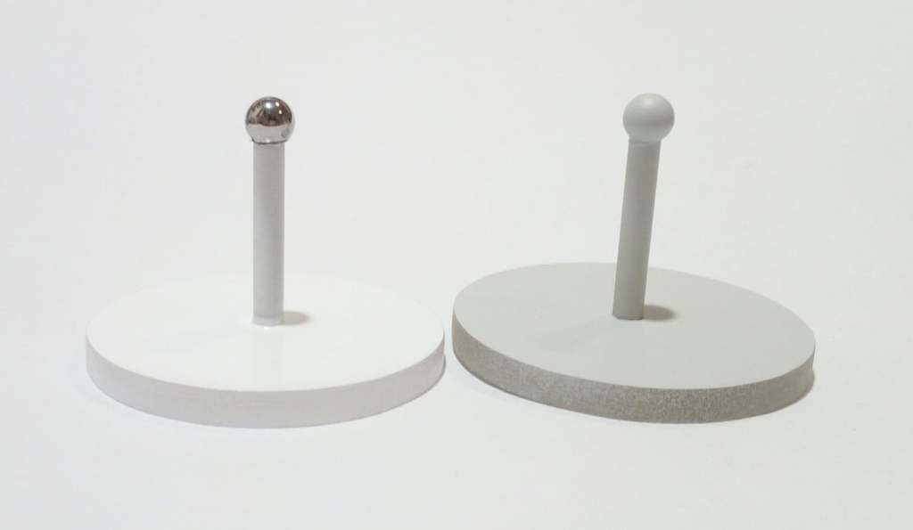
A matte plastic grey sphere and a reflecting metal one was inserted inside the cylinder, fully illuminated, and a succession of frames were acquired to visualize the possible presence of single luminous points.
If the LEDs were visible on the specular surface of the metal sphere or an uneven illumination on the plastic sphere, it would mean that the diffusion is not optimal, giving rise to shadows and unwanted reflections.
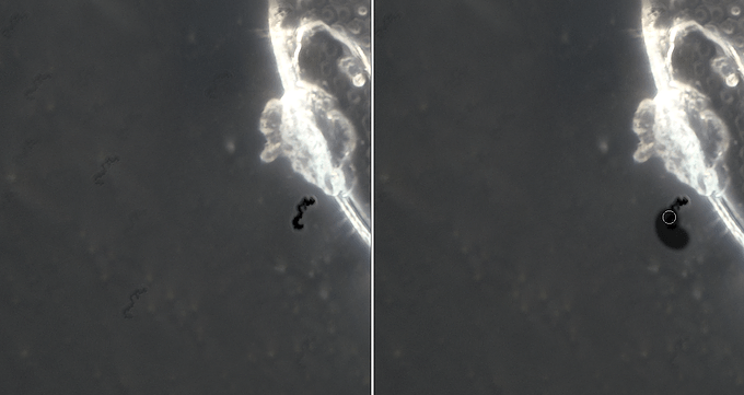
The result is visible in the two images below. The plastic sphere is illuminated homogeneously over the entire surface, and the test using the metal sphere (a test that is among the ‘worst’ because very sensitive to detect spot of lights) is extremely positive. You can barely see the individual LEDs bands, while the black circle is simply the lens of the objective reflected on the surface of the sphere.
In order to get illumination coming from above as well, a white reflective plastic cover, drilled in the middle to allow the lens to pass through, “closes” the diffuser.
The illuminator has been conceived to be able to acquire subjects with vertical photographic system, even if it is possible to adapt it for horizontal systems, as for example for those who photograph insects. The internal diameter of 10 cm is sufficient to be able to acquire most amber samples placed inside a transparent laboratory glass container (beaker or petri dish). Being open at both ends also allows you to manage the type of background you want to use, in order to increase the visibility and contrast on the subject.
In addition, the acquisition times are reduced by an order of magnitude of 10; if I usually acquire images with exposure times included between 1/20″ and 1/10″, this system allows you to work with times of 1/125″ – 1/250″ (see example described later), further reducing the possible presence of micro-vibrations. These times obviously can still be further reduced by increasing the power of light, but at the expense of excessive heating inside the nuclear furnace, with consequent risk of melting of the core (read “the amber”) and devastating environmental consequences (read “my portfolio”). A project currently underway, adaptable to all rail conceived for extreme-macro systems, will allow the LEDs to be turned on and off only during the image acquisition phase, minimizing the power consumption, extending the life of the LEDs and , most important, avoiding heating of the system.
Most of the components of the system is printed with FDM (Fused Deposition Modeling) technology, in plastic material ASA 275 (Acrylonitrile Styrene Acrylate) resistant to temperatures up to 85°C and UV, is powered by a 12V and 4A, not resulting particularly bulky and fits perfectly to my current needs.

First results
A first test was carried out on a mite fossilized inside a Baltic amber, a subject that has already been acquired previously using two 20W LED panels and a semi-transparent white double-walled plastic diffuser as lighting. With the same step (15µm) and microscope objective used (a 2.5x Mitutoyo objective, pushed to 4.7x), the camera acquisition speed was respectively 1/13″ (with the double panel diffuser) and 1/125″ (with the cylindrical diffuser), thus also reducing the waiting time to complete the necessary shots.
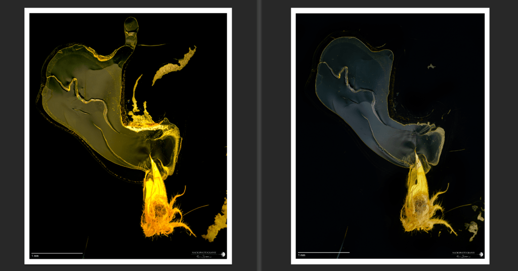
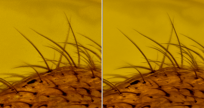
It is curious to note that the lamellar structures that characterize the inside of the amber show differently in some areas (see next images). The different orientation of the light source affects a differential reflection of these specular surfaces that have a sub-micrometer thickness; this aspect requires more in deep analysis; it is possible also that the heating created by the LEDs can slightly modify these delicate flat structures.
The image is more contrasted with the use of the cylindrical illumination system, the colors lose much of the yellow dominant, allowing a better differentiation of the shades of color present on the surface of the organism.
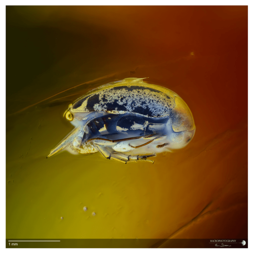
Here is a very nice flower of Oak, acquired with this lighting system:

These first results are undoubtedly encouraging, and others will follow soon, with subjects of different shapes and characteristics …
Happy Stacking !
Creating a bar scale
It is important, whenever you want to publish a subject’s image, to add a reference that indicates the correct size. If for macroscopic subjects, a coin, a ruler, or a special bar scale is sufficient, for subjects with sub-millimeter dimensions, the operation may seem more complicated.
It could, but it really is not.
To add a reference bar, you must, first, be able to measure the value (in pixels) of the length of a metric reference within the lens’s field of view. This is done by capturing a photo of a reference millimeter or micrometric scale such as, for example, the one visible below.
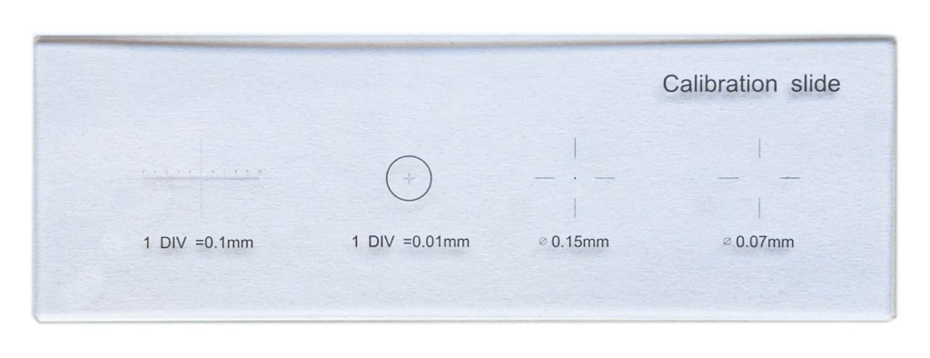
This is a simple microscope slide, in which different sub-millimeter scales are engraved, ranging from tenth to hundredth of a millimeter; rulers can also be used for low magnifications.
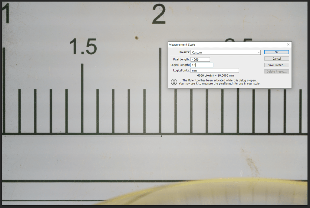
You must simply place the slide in front of the lens, focus and photograph it trying to possibly have the micrometer scale parallel to the base of the frame. The image thus captured is imported into a graphics program (in my case I use Adobe Photoshop).
Calculates the number of pixels that are included within two (or more) notches. In the example below, the number of pixels between notches with values of 1 and 2 (i.e., 1 centimeter in this case) is 4066. So, we have 4066 pixels included in a space corresponding to 10mm, each pixel has a dimension of about 0.0025mm (or 2.5μm).
Knowing the number of elements that characterize the camera sensor, it will be easy to calculate the size of the field covered by our lens.
The SONY A7RII camera model I use has a 35.9x24mm sensor, consisting of 7952 x 5304 elements; for other camera models, the value is easily found in the instruction booklet that accompanies the camera, or by performing a simple search on the web. Multiplying the size in mm of the single pixel by the number of pixels present on the sensor (or in the image, side-to-side), I can obtain the size of the field, that is, in this case 0.0025 mm x 7952 = 19.88mm, just less of 2cm, as already visible by looking at the previous image.
The calculated value varies depending on the objective, and the optical configuration used. Knowing a priori that set-up is used, we will consequently know the size of the field covered by our objective and we can, for example, create “ad-hoc” scale bars that can be reused whenever we acquire a subject with a predefined set-up. In Adobe Photoshop you can even create a library that you can easily access, and set the correct working scale depending on the system used:
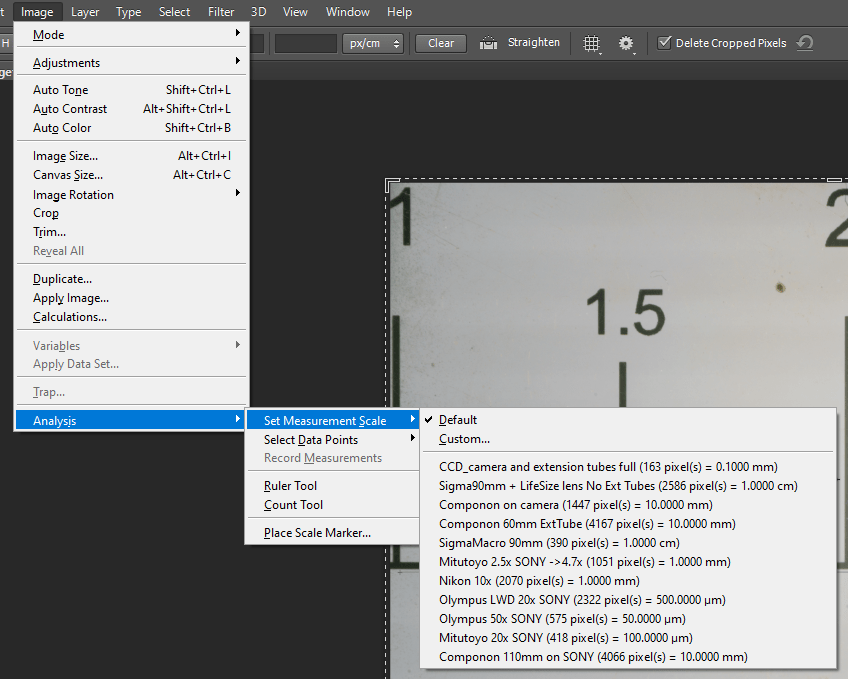
Once the subject is captured, it is only required to select the setup and activate the “Place Scale Marker…” menu to place the reference scale bar in the final image.
Happy Stacking!
Vibrometer !!!
Have you ever thought about measuring the vibrations that are present in the room where your macro-extreme acquisition system is installed? Or at least evaluate the efficiency of the mat, the rubber pads, and the springs used to dampen the vibrations that inevitably make your acquisitions blurry? A solution that exists, or rather a small software, that you can install on your cell phone (for Android, but must exist also for IOS), is called: Vibration Meter.
You can download it for free from the Google Play platform: https://play.google.com/store/apps/details?id=kr.sira.vibration&hl=en&gl=US
This simple application, once properly calibrated, allows you to determine the smallest vibrations in the environment such as those caused by the camera (obviously we are talking about Digital Single-Lens Reflex (DSLR)) or the movement of the track that moves the camera system.
In the image below you can see a screenshot made with my smartphone:
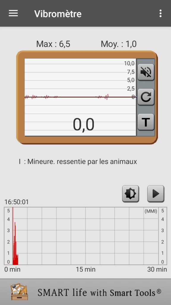
The vibrations recorded in the upper graphs correspond to the steps I took around the table on which the capture system rests, and I didn’t step on my feet! The application can record the passage of cars under the house and the step that the motor makes on the endless screw between acquisition and the next.
The application installed is freeware, but you can also buy the full version (it costs the exorbitant amount of 1.99€) allowing you to export in .csv format the recorded data and export the images. If you want to have access to a short tutorial on how to use this app, there is also a video accessible on youtube: https://youtu.be/LlYcJJ5FKOU , or more easily, below 🙂
